Showing posts with label 3. Pipes and fittings. Show all posts

Friday, September 23, 2016

3.2 Valve Spec & Purchase

What Are Valve Specifications?
Similar to piping specification, but provides you the guide to what those valve commodity codes on the piping specification means.

Typical information includes:
1) Commodity code
 Commodity codes are usually a long string of text for example the below I have seen:
*VOEACCM
*VAACE6PM
*CVV1137YY

These codes is how Company or Contractor label their valves in a systematic manner based on the specifications below.

2) Type of service
The service fluid the valve is recommended for.

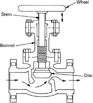
3) Materials of construction
 Material of construction of the body, stem, handwheel, disc, seat. 
Type of body constructions for example forged, casted, machined, etc.. (Body commonly casted)

3.1)Type of Trim
This is the material specification of the disc and seat. Read API 600/602 for a list of trims typically carried by vendors and their applications. They range from a number from 1 to 12 and this numbering is not in order of anything.

Trims can come in hard or soft material. Where Hard here refers to hard facing material such as stellite and martensite stainless steels (400 series) and soft refers to the usual 316. There are other classes of trims non-API for example resilient soft seats used in harsh chemical service in typical resistant materials such as PTFE, PEEK, VITON and many more, theses resilient soft seats are usually much susceptible to damages and would require increased frequency and cost of maintenance.

3.2 ) Packing construction
*Packing compression type: with or without Bellville springs 
Teflon or other Polymer packing
Steel wire reinforced graphite yarn packing 
Or a mixture of graphite yarns with pure graphite rings (Harsh applications)

4) Type of Valve construction for eg.
Ball - 3 piece bolted, 2 piece screwed
Globe/Gate - bolted bonnet, screwed bonnet, welded bonnet, pressure seal
Butterfly - wafer type, lug type
Check - Piston, swing disc, lift disc, butterfly double disc, hoerbiger type

5) Flow Pattern
High/Low CV
Full bore / Reduced bore.
2 way, 3 way, 4 way flow.

6) Valve Testing and Inspection
Most common testing and inspection standards for new and repair of valves will comply to API 598.
Refer to it for exactly what needs to be tested and inspected to verify that a valve is fit for service. It fulfils the basic requirement to ensure valves qualities.

Purchasing Issues
Some thing you might ponder about during purchases:

Why are certain brands so significantly cheap / expensive? 
Let us break down a valve into its individual components to analyze. When you breakdown to this level you would realize each valve is intricate when you perform the installation and maintenance. 

However from an inexperienced purchaser/piping designer point of view, they will consider a valve as "it's only a valve." without realizing valves are part of a major problem in a plant should it be of inferior quality, Potential problems we might face will be mentioned in  Section 3.7 Valve Repairs.

Potential areas observed that manufacturers saves on that are less investigated by purchasers/piping designers:
* Packing design and material (Potentially results in low MTBF, frequent leaks)
* Body material (Composition of ingot material from inferior source not meeting composition req'd)
* Casting method (Casting method/flow plays great importance in strength of material)
* Quality Control (Despite documentation, hidden lapses and doctored inspections would still be present from some overseas manufacturers especially in China/India where QC seems haphazardly done. Nevertheless, I have still seen quality products from China and India, of course at a higher price. So nationality of these valves shouldn't be stereotyped, but rather the quality control process and how the purchaser would like to manage these issues should these lower cost destinations needs to be specified.

Point at the end of the day... You usually pay for what you get.

Saturday, November 28, 2015

3.6 Steam traps

Common Steam traps types

Thermodynamic
Application
  • Steam tracer lines or small steam headers
  • Low flow rates
  • Good for startup air venting, 
  • Compact in size
Common problems
  • Clogging
  • Disc stuck or worn
  • Seat worn
  • Unreliable, requires frequent PM
Troubleshooting
  • Check for cycling noise to verify functionality. No cycle indicates Failed in open, fast cycle indicates flow too high or faulty. 
  • Open blowdown to remove particles, if any.
  • Remove cover to lap seat and replace disc if blow down does not works, 
Problem faced during maintenance
  • Steam cuts on seat, as it may not be made from harder material like the disc.
  • Some welded to pipe models where lapping needs to be done, has to be performed in the field.
  • Old isolation valves to these welded traps could be passing steam, as such it is either difficult or in some cases dangerous to perform maintenance.
  • Old isolation valves could be leaking steam at packing and could only be repaired during shut down. 
  • Mix up of steam trap models, ie. Spirax Sarco thermodynamic traps TD42 comes in various models for high pressure rating, high condensate flow, low condensate flow rate and they may use different disc types and these could be mismatched by maintenance operators.


Thermostatic bimetallic
Application
  • For low to mid flow rates such as large or HP steam distribution headers
  • Long life span
Common problems
  • Clogging at strainer, ball/seat area or bimetallic plates
  • Valve setting runs out.
Troubleshooting
  • Particles trapped on bimetallic plates n valve assembly will impede on operation, blowdown if possible, clean assembly and adjust valve setting. 
  • Servicing will usually fix this steam trap, internal assemblies can be rather costly to replace. Costs usually about 40-50% of a new bimetallic steam trap, especially for high pressure versions.
Problems faced with maintenance
  • Open blowdown to remove particles, if any.
  • Expensive spare parts, difficult to justify for PM budget until major system breaks down eg. pipeline puncture.
  • Steam cuts at the valve assembly, if none blow to remove dirt with compress air. 
  • Need training for maintenance operator to adjust bimetallic valve properly


Balanced pressure
Application
  • Venting air during start up
  • LP Steam headers and small steam equipment
  • Long life span
Common problems
  • Stuck capsule
  • Punctured capsule
Troubleshooting
  • Open blowdown to remove particles, if any.
  • Clean or replace capsule
Problems faced with maintenance
  • None so far.


Ball Float
Application
  • For High condensate flow rates, such as condensate discharge of steam heaters.
Common problems
  • Does not vents trapped air in system, will requires a air vent mechanism.
  • Air vent mechanism stuck
  • Float mechanism stuck 
Troubleshooting
  • Open blowdown to remove particles, if any.
  • Particles trapped on valve assembly will impede on operation. Remove and clean assembly if stuck.
  • Steam cuts at the valve, if none blow to remove dirt with compress air. 
Problems faced with maintenance 
  • Thin and small width graphite gaskets used, prone to damage followed by leakage during start up. Ensure installation is monitored by competent supervisor.
  • Provide IOM to maintenance operator, assembly can be confusingly installed in wrong direction and etc at times.
  • Bolts may be stuck if it was never serviced throughout, prepare additional bolts.

Inverted bucket
Application
  • Vents trapped air very well
  • Moderate condensate loads,
Common problems
  • Bucket assembly stuck
  • Loss of prime
Troubleshooting
  • Open blowdown to remove particles, if any.
  • Check for cycling noise to verify functionality. Close downstream valve to prime the trap with condensate to restore functionality.
  •  Remove for service or repair if priming does not work.
Problems faced with maintenance
  • Provide IOM to maintenance operator, assembly can be confusingly installed in wrong direction and etc at times.
  • Bolts may be stuck if it was never serviced throughout, prepare additional bolts.

Tutorials
Visit Spirax Sarco tutorials for more information regarding sizing, application, maintenance of steam traps. Its a brilliant webpage.
http://www2.spiraxsarco.com/resources/steam-engineering-tutorials/steam-traps-and-steam-trapping/why-steam-traps.asp


General Maintenance Guidelines
Steam traps are automatic valves meant to eliminate condensate out of steam systems to improve system efficiency, as presence of condensate reduces heat transfer. It is one of the most neglected item in a process plant, as such it poses a risk to steam system blow outs.

But this device appears to be harmless and runs on its own. Why bother? The amount of discharge is insignificant to cause any damage. No!

When steam trap maintenance is absent, wear and tear tend to cause it to pass steam. Over time, as it gets excessive, significant two phase flow within the system will take over and cause erosion and pitting internally (Imagine sand flowing at high velocity thru the pipes which peens and grinds down on the surface), these effects enhanced with CUI in corrosive and humid environment, which eventually leads to pipe puncture.  (Some photo of the leaks to be attached.)

This is a well known problem in the industry, as steam operate at much higher velocity about 30 -60m/s, when it enters condensate stream heavily, it increases velocity of the condensate, therefore:

  • The flowrates increases beyond the design for condensate flow,
  • Condensate droplet impingment prevails which can be detrimental to tees and elbows over time.

Good design practices
  1.  keep traps as close to condensate lines as possible and keep the return lines as insulated.
  2. Size the condensate line for flash steam flow, assuming 15 to 20% traps are passing
  3. Make use of flash drums closer to point of condensate generation to minimize effect of flashing steam in long condensate pipes.
  4. Assign separate condensate lines for the various steam pressures ie. LP, MP, IP, HP.
  5. Minimize sharp bends and injection points by using swept tees, 45EL or diffusers respectively.


Schedule & Recording keeping
A schedule should usually be available to determine steam trap survey on regular intervals and these can vary depending on willingness to invest or past operating experience basis, for example. If otherwise please develop such a schedule to ensure steam traps maintain in good condition.

Regular schedule
  • A Check on all steam traps in the plant every 1 year
  • Blow down on all steam trap line blowdown valve every 3 months
Risk based schedule
  • A Check on all thermodynamic traps every 6 months
  • A Check on all mechanical traps every 2 years
  • Blow down on all high particulate lines every 1 month
  • Blow down on others every 6 months
Survey and Repair Records
  • These records will allow future generations to make decisions whether to replace a steam trap or not, as some could be costly.
  • Survey records shall be kept as there could be thousands of steam traps in a plant and it will not be easy to manage the repair and maintenance effectively without one.
  • Repair records shall be kept so recurring problems could be identified for redesign, decisions could be made whether to invest in new steam traps or spare part replacement.
  • Repair records could also help to develop spare pares strategy as we now know the usage pattern. This strategy will also be effective to help cost saving intiative in spare parts purchase during construction of new plants

Troubleshooting & Survey
Simple methods to identify faulty steam traps
1) Temperature method
Run a temperature gun on the pipe before and after the steam trap. As pressure difference exist due to resistance and separation, there will be a temperature difference across the trap. This is the most suitable test on higher pressure steam lines where dT across the trap is relatively higher. If there are no temperature difference across the trap, it is likely passing steam.

Run the temperature gun on the trap. Cold could mean its failed close/clogged. Hot could means its working or passing steam.

2) Visual method
Open vent/drain valves before the steam trap (live steam will release), after the steam trap (flash steam will release).  If nothing is released after a long wait the steam trap has failed in close position, if all you see is steam blowing out in a jet then it has failed in the open position.

3) Listening - audible noises
This method involves holding a long metal rod, one end touching the trap and one end touching your ears. The effect of condensate passing can be confirmed when cyclic action of the steam trap is heard.

4) Listening - Ultrasonic testing
This is the most reliable method and will probably require engaging and external vendor/operator to perform the task. Steamtrap vendors such as Spirax Sarco & armstrong intl would normally offer complete steam trap survey services for an entire plant at a nominal fee.

Watch this video for a detailed guide with illustration to troubleshooting the traps by Armstrong intl.
Guidelines for Steam Trap Troubleshooting: http://youtu.be/smjuAEZOrlk

Tuesday, August 4, 2015

3.5 Stud bolts / Hex nuts and their relation to Flanges

Stud bolts and nuts

Stud bolts and nuts are the most commonly used fixtures for joining. 
They are most commonly used to join pipe flanges, heat exchanger shell girth flanges and many more. 


Reasons for replacement ?
This topic came to my mind, as I am required to purchase replacement Stud bolt and nuts for several heat exchangers girth flanges. The more common reasons for replacement in the process plant and specifying them correctly are due to the following:


1) Corroded stud bolts and hex nuts, 
a) Corrosion sometimes can be so severe that the diameter of the bolt is below minimum required diameter handle the bearing stresses. 
b) Corrosion is common occurance at the crevice between the flange bolting hole and bolt surface. 
c) Due to the recessed surface of the pitch on a bolt, they tend to catch dirt and corrosive particles more easily.
- The norm is to just replace the studbolt/nuts with same material/spec on wear and tear
- An upgrade can be performed to reduce maintenance cost, but remember take care of galvanic corrosion when using bolts of a seemingly better material on susceptible pipe lines, to avoid ill effects of "fixing problems to cause more problems".


2) "Frozen" bolts
a) This can be the resulting combinations of either corrosion, thermal expansion, over torque, loss of lubricant, crossed threaded bolt-nut, etc etc etc.
b) this is very common on very hot services approx above 80degC
 - These are usually broken free by cutting the bolt due to ease, which means replacement. 
- The better & toughy fitter may attempt to break free for you after applying anti-seizure lubricant but will take up much time.


3) Needs to be specifically defined to the correct vendor 
a) Contractors may not check or calculate for you, if your drawing does not show the exact length or details at all.
b) Flange/Pipe stockist may not carry stud bolts and nuts.
c) Different equipment uses different flange standards, which means different size and lengths of bolts and nuts. We shall discuss this later.


Standards for Bolts/Nuts
The most commonly used standards for defining Stud bolt and Hex nuts in the process industry are the following, due to the wide range design temperature it can handles and its superior market availability.
ASME B193 Grade B7 - Steel Stud bolts
ASME B194 Grade 2H - Steel Hex nuts 

For ASME B193 B7, it will handle from -29 to 427degC.
For higher temperatures, we will need to move up to grade B16, grade B8C1 and so on.
For cryogenic temperatures, use A320 L7, grade A320 B8C2 and so on.

For ASME B194 Grade 2H. it can handle -29 to 537degC.

The grades of the stud bolts and hex nuts will be marked on their body, provided they have not corroded.

Standards for its threads
Most commonly used standard for stud bolt threads is the Unified Thread Standard to ASME B1.1:
UNC - UN Course thread, common for up to 1", where bolt diameter size increases with decreasing thread pitch.
Others include:
8UN - 8 pitch thread, common for bolt/nut larger than 1")
UNF - UN Fine thread
UNEF - UN Extra Fine thread
UNS - UN Special thread

Thread pitch refers to the number of turns per inch length.

Standards for Flanges
Most commonly used standards for defining pipe flanges in the process industry are the following:
ASME B16.5 - Flanges from 24" and down
ASME B16.47 - Flanges from 26" - 60"

Read these standards and they will have tables to guide you on the number of bolts, length of bolts and size of bolts required for each type of flanges/pressure rating. You could also request a vendor version of these references from your Flange stockist.

Take note for ASME B16.47, there are Series A and Series B flange which do not share the same bolt hole sizes. Series A is adapted from MSS SP-44, and type B is adapted from API605 as part of ASME effort to standardize the dimension of flanges. 


Calculation for bolt length

L = 2(n+f+rf+s) + g + etc

Where
n = Nut thickness
f = Flange thickness
rf = Raised face thickness
s = Free length (1/3 diameter of bolt)
g = Gasket thickness
etc = additional fixtures such as tube sheets, orifices, additional gaskets, etc.


Additional Information
Collar /Jack bolts
These are additional bolts which sometimes or rather most of the times comes with heat exchangers.
The purpose of these bolts is to secure the tubesheet on the shell, should maintenance be only carried out on the channel heads.

But these bolts are usually more corroded or "frozen" than the regular stud bolts due to the irregular shapes it may have. Some of the irregular collar bolts may not be available off the shelf, as such do pre-fabricate some spares in times of need.  Check out the reference below for pictures which may better explain things.


Torquing the Flange bolts
Why torque the bolt to the recommended setting? You will tend to hear these from the contractors first:
- "I did not torque any bolts/nuts for the last blah blah years and they worked fine"
- "You don't need to torque, just go for the tightest"
- "It will not explode, dont worry"

My opinion goes to say that I agree to their advice for most services operating under ambient temperatures with exception to what to be mentioned next. One shall start obeying the rules of torquing the flange bolts when things starts going extreme ie.
- Very high temperature & pressure (HP boiler steam drums and reactors)
- Very large variation in operating temperature (Cryogenic loading/vaporizer lines)
- Very large variation in ambient temperature (Temperate location experiencing 4 seasons)
- Very large variation in operating pressure (Pulsating line, swing adsorption, etc)

Be very worried, unless you are prepared to seal the leaks on-line which can be very costly. Costlier than a 3ft torque wrench. 

Theory underlying the need for torquing:
- The forces from the bolt torque will affect the way gasket seats on the flange faces
- Uneven seating faces due to random tightening will cause leaks
- Over tightening will cause some solid material gaskets to yield or crack.

Sunday, March 29, 2015

3.4 Insulation

Insulations for process piping

Insulations are installed for the very obvious:

1) Heat conservation for economic purposes
-These are such as, preserving heat within a hot steam pipe during transfer from a boiler to the steam appliance
-or preserving cold coolant during transfer from air con condenser to the room evaporating unit.

2) Personnel protection purposes
- These insulation are usually thinner, to prevent direct contact between man and hot surface
- Insulation material can be replaced with a suitable cage, if heat needs to be dissipated for some reasons, or corrosion under insulation(CUI) is prevalent on the piping circuit.

3) Types of insulation
Mineral wool/Rock wool
This material is commonly used for hot service.
Operating range: 0 to 250(glass)/760(stone)/1200°C(ceramic)
It is usually white/yellow and sold in rolled bundles of wool. The process fluid used with this is usually non flammable, as mineral wool can induce fire, despite it being "fire resistant". Mineral wool can catalyse oil, breaking down it down to lighter and easily combustible components which makes it more dangerous. Note that it also absorbs moisture easily. Always wear gloves when handling, it irritates and makes the skin itchy.
Source: Wikipedia


Calcium silicate
This material is usually used for hot service.
Operating range: -18 to 650°C
It is usually whitish, pre fabricated in blocks and appears like chalk. Good for use with hot oil service, as it does not catalyse oil. Also commonly used for fire insulation, see photo below for an example of a ductwork requiring fire protection rating.
Source: Wikipedia


Foam glass
This material is commonly used for cold or hot service.
Operating range: -260 to 480°C
It is usually black color, pre fabricated in blocks, has the texture and characteristic of somewhat a harder styrofoam and can be cut to fit.
 Source: Wikipedia


Polyurethane
This material is usually used for cold service.
Operating range: -210 to 120°C
It is usually yellow or white color, requires injection of PU foam into preinstalled cladding put in place around the piping/equipment.
 Source: Wikipedia


Perlite
This material is usually used for cold cryogenic service.
Comes in sacks of white loose powder or compressed blocks. Very good for cold service, however needs to be kept dry for optimum performance. Usually used in N2 purged spaces or vacuum spaces.
 Source: Wikipedia


Vacuum jacketed insulation
This is usually used for cold service in cryogenic applications or hot service in thermoflasks.
It is very good method for preserving energy and vacuum level needs to be checked on intervals, if lost, needs to be replenished by hooking up a vacuum pump to "pull vacuum". Tell tale signs of losing vacuum are sweating on the exterior of vessel or algae formation.
Source: technifab.com


Installation of Insulation
 The sizing of thickness and materials are very much dependent on application, process fluid and heat transfer rates to achieve less than 50°C on the external cladding surface for personnel safety reasons, as 50°C is usually the rule of thumb "ouch" threshold for humans.

During actual installation, we have no time to calculate the above, therefore tables are usually prepared before hand by the engineers, to advise the right insulation material and thickness. These information can usually be found on the piping specification which will specify different thickness for each application and the different temperature ranges.

eg. on the P&ID, isometic dwg or line list, the insulation fitter will have to interpret the following:
2"-HOTOIL-2330-1DC1A-1P    ----> 1P usually refers to 1" of personel protection insulation.
2"-HOTOIL-2331-1DC1A-2H   ----> 2P usually refers to 2" of heat conservation insulation.


Maintenance of Insulation
Insulation material when installed bare will disintegrate when exposed to effects of the environment, as such they are usually protected by cladding of aluminium or stainless steel material.
A sealant is then applied to the gaps where the cladding overlay each other.

Perlite insulation is different, it is usually dumped between the double skin section of the vacuum jacketed piping or vessel, as such it is easier to maintain.
 Source: Wikipedia

1) Avoid stepping on insulation cladding during maintenance work
2) Check yearly to ensure sealant between cladding are in place
3) Install inspection ports for checking corrosion and thickness monitoring on the pipelines/vessels, these pockets will also be good for inspection the insulation condition beneath the cladding
4) Top up insulation material when they deplete under environmental deterioration
5) Avoid re-routing insulated piping to where they will be exposed to moisture, vents, drains and process mists areas

Thursday, January 29, 2015

3.3 Valve types, parts, accessories and application,

Gate valve
Application: on/off. Usually use for complete isolation.
Typical serviceable parts: Stem, seat, wedge
Types: Solid wedge, flexible wedge, split wedge.
What to specify when buying: Pressure rating, temperature, flow rates, process medium, end connection type, bonnet connection type, design/material of the body, disc, seat, stem, packing.

Image Source: profmaster.blogspot.com

Globe valve
Application: throttling. Usually used for throttling liquid flow. Large pressure drop across due to significant change in direction in design.
Typical serviceable parts: Stem, disc, seat, packing.
Types: Angle, Y-type, straight type.
What to specify when buying: Pressure rating, temperature, flow rates, process medium, end connection type, bonnet connection type, design/material of the body, disc, seat, stem, packing.

Image Source: www.globalspec.com  /  Mcgraw-hill Publishing


Needle valve
Application: throttling. This valve is exactly like globe valve, except with a tapered seat. For more info, see globe valve above.
Typical serviceable parts: Stem, disc, seat, packing.
What to specify when buying: Pressure rating, temperature, flow rates, process medium, end connection type, bonnet connection type, design/material of the body, disc, seat, stem.


Diaphragm valve
Application: on/off. Usually used for very corrosive chemicals to protect valve trim.
Typical serviceable parts: Stem, disc, diaphragm.
What to specify when buying: Pressure rating, temperature, flow rates, process medium, end connection type, bonnet connection type, design/material of the body, disc, seat, stem, diaphragm
Image Source: www.globalspec.com


Ball valve
Application: throttling or on/off. Usually use for quick opening with less torque requirement.
Typical serviceable parts: stem, handle, ball, seat.
Types: straight, angle, L-port, T-port
What to specify when buying: Pressure rating, temperature, flow rates, process medium, end connection type, body connection type, L/T port arrangement, design/material of the body, ball, seat, stem.
Image Source: www.kitz.co.jp

Plug valve
Application: See ball valve, except that a turnable plug with a bore is used instead of a ball.


Butterfly
Application: throttling or on/off. Not suitable when opposite sides of fluid have large differential pressure, makes the valve hard to open, not tight sealing.
Typical serviceable parts: Stem, disc, seat, packing.
Types: wafer type, lug type.
What to specify when buying: Pressure rating, temperature, flow rates, process medium, end connection type, bonnet connection type, design/material of the body, disc, seat, stem, packing.

Image Source: www.kitz.co.jp


Check valve
Application: Non-return flow.
Typical serviceable parts: Disc/ball, seat
Types: Swing Disc, lifting disc, butterfly, ball,
What to specify when buying: Pressure rating, temperature, flow rates, process medium, end connection type, bonnet connection type, swing/lift/flap arrangement, design/material of the body, disc, seat.
Swing type check valve
Image source: www.kitz.co.jp


Lift Type Check Valve (Similar to globe, but w/o a stem)
Image source: www.jdvalves.com


Safety valve 
Note: Usually referred to many as PSV (Pressure Safety valve for gas systems, opens when overpressure detected) or PRV (Pressure relief valve for liquid systems, opens based on proportion of overpressure)
Application: Pressure relief or thermal relief application. Selection based on pressure and flowrates usually sized according to API 520 PSV Sizing. ASME Section I & Section VIII also denotes their required settings for allowable tolerance on set pressures and blow down(closing back pressure)
Typical serviceable parts: Lever, spring, adjusting ring, disc, seat, bellows.
Types: Conventional, Balanced pressure, Pilot operated, Power operated,
What to specify when buying: ASME Section I (w/ Lever, open bonnet, 2 adjustment ring configuration with U stamped for boilers), ASME Section VIII (Any configuration with UV Stamped for general process), Other design (with or without lever, open or closed bonnet, with or without bellows(back pressure compensation).) , Pressure rating, temperature, flow rates, process medium, end connection type, design/material of the body, disc, seat, stem,
Typical ASME Type I PSV.
Image source: Consolidated Catalogue Type 1900.


Image Source: spiraxsarco.com


Detail of PSV with Bellow/diapgragm
Image Source: spiraxsarco.com


Pneumatic Actuator - variable control

Pneumatic Actuator - on/off control
Air being a more powerful actuating media suitable for explosive environment, is also used for on off control of a valve by an piston actuator.
It comes with a solenoid valve which allows air into itself, the electrical component(solenoid valve) is smaller and less costly to own, as compared to having a huge electrical component with hazardous area protection which could cost significantly more.

Solenoid Actuator - Usually used for on/off control, for where quick opening and closing of the valve is required. Used on small systems, or when used for saving cost on pipelines which requires explosion proof set up(see Pneumatic Actuator above).

Motorized actuator - Usually used for on/off control, for where more torque is required to actuate the valve, motor can be powered by electrical power, hydraulic power or pneumatic.

Handwheel, handle, disc, seat, bonnet - See above photos on valve description for a clearer picture.
The bonnet-body of these valves could be integral or separable. Advantage to be separable if the valve is costly to purchase as replacement. ie. Exotic material or CTE/BAM tested are very costly to purchase, disadvantage is that the leak sealing will not be as robust.

Spoke wheel pulley - Used where valves are installed in high location, where access is inconvenient.

Extended spindle - Used on cryogenic systems, where high humidity leads to icing which eventually ices up the entire handwheel, as such denying user from operating the valve. A long handle alleviates this problem.

Pressure rating - American systems, 150#, 300#, 600#.... sometimes it may denote 600WOG instead which is equivalent. WOG stands for water, oil gas. Read the post on Piping Specs for details on how pressure rating come about.


Valve Sizing for pressure loss (liquid)
dP = SG * (41720Q/Cv)^2

dP = Pressure loss (kPa)
SG =  Specific gravity (dimensionless)
Q = flowrates (m^3/s)
Cv = Coefficient of flow (check valve specification from manufacturer)

For gas/steam, use its specific formula for Cv.


What to specify when buying
The above will help you the understand a valve. With regards on how to specify a purchase to the procurement or vendor when sourcing for valves, refer to the short write up on this section:
3.2 Valve Spec & Purchase

For each of these valves, the essential details to be knowledgeable to select the right valve for the right application. If in doubt, consult manufacturer's application engineer for advice.

Saturday, January 17, 2015

3.1 Piping specifications

Piping specs

What are these? Whenever a plant is designed to run a certain process, piping to carry fluid will be involved. This spec will be developed by the piping engineer for any user to reference and select the specified pipe material, thickness, rating and many for the fluid service in future. The content of piping specifications varies through out different contractors, so dont worry if one item is missed out, however the critical ones shall be present.

If there are no company standard piping specs available and one needs to be specifically developed for the project, it should preferably be developed from an existing database for similar services. If otherwise consult the experienced materials , reliability, maintenance and operations specialists, the more the merrier to eventually form the most probable opinion based on experience to mete it on trueform.

This is a vital document for the following activities during projects, so have it ready during the early periods of the design phase in a project.
P&ID & Detailed engineering - Specifying pipes, fittings and indication of line numbers
Equipment list - Specifying line code number, valve code numbers
Proj QC - Verification on conformance to codes
Maintenance - Specifying pipe and fitting replacement
and many more.

What information to look for or include in the piping specs

These are what you would normally find on the piping specification table from top to bottom

1. Fluid service
  • Types of process fluid this specification can handle, the number of fluids are not limited in each pipe spec, to reduce the pages! 


2. Flange pressure rating and type
  • The ratings are derived usually from ANSI or DIN/ISO data tables, select one that could meet the pressure and temperature specified on the PFD or design specifications.


3. Design temperature/pressure of the pipeline
  • This may not be necessary to include as it may confuse designers with equipment design temp/press. This item needs to be verified with thickness calculation and process engineers to minimize change logs.

4. Corrosion allowance
  • This is derived from corrosion rates for similar pipe material and process fluid from existing data. Corrosion allowance(mm) = Corr. Rates(mm/yr) X Plant Design Life(y)


5. Pipe material

  • This is usually specified in its ASTM name, so procurement could use them to source accurately, suppliers will understand in an instant. Eg. CS ASTM SA106, Gr. B SMLS refers to Astm code 106 grade B seamless carbon steel pipe. 
  • The pipes comes in std length of 6m. Other lengths are also available but uncommon and subjected to increased lead time. 


6. Pipe size and thickness
  • This will come in a table format, as pipe sizes and thickness will vary to meet design pressure requirements. It is developed from the calculations in ASME B31.3 process piping codes: t=[PD/2(SE+YP) +tc+tf ] x [100/(100-tf)]
t= Thickness of pipe, in
P=Design pressure, psi
D= OD of pipe, in
S=Yield strength of pipe at design temperature, psi (Based on material)
E=Weld efficiency, dimensionless (from 0.85 to 1 depending on joint method)
Y= Derating factor, dimensionless (usually 0.4 for steel material below 900F)
tc = Corrosion allowance, in
th = Thread depth, in (If threaded connections are used)
tf = tolerance factor, dimensionless (Usually 12.5% depending on pipe maker)
  • If designing for pipeline projects, you may refer to B31.4 for less stringent calculation, for marine systems refer to ABS/LR/DNV or the class design codes, as calculations may differ. However the principles remains the same. 


7. Fitting size and rating

  • Similar to pipe calculations but different calculations, will be specified in a specific post in future.


8. Flange size, spec and rating
  • Specified type of flange and its rating to meet required pressure requirement at its design temperature. 
  • Type of flange face and joint to equipment/pipes, will be specified in a specific post in future. 


9. Valve size, specs and rating
  • There are different valve material, types and configuration for each range of the sizes.  Select the suitable type for the service, ie. On/off, throttling, low pressure loss, quick opening, etc. Explain on later posts.


10. Brand connection types & its fittings.
  • Different size pipes(run) may use different joints types which offers similar strength at a lower cost. Reason being a socket type joint on. 1" pipe may be strong, but not on a 4" pipe. The recommended connections are specified in the last section
  • Tees are used for same size connections.
  • Reducing tees for a reduced branch
  • O-lets, weld type, socket type, thread type allows to stub on a pipe to the main with better strength.
  • Stub in, most economical way of connecting branch pipes.
  • stub out for one size smaller branch


Sample piping specification for reference to the above explanations.
Source: ligo.org